中文
ENGLISH
中文
ENGLISH
We love to help our customers improve their vowin.cn' target='_blank'>product designs by offering insights gleaned from actual case studies. Recently, we worked with one customer to help them build two multi-cavity molds for a product that will be used in a high temperature environment. From a study of these product development details, we’ve gathered together four tips we want to share that can help you optimize your designs when preparing your next plastic injection molding project.
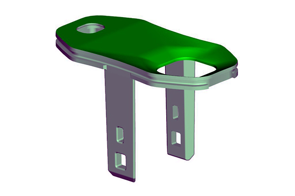
This part was made from high-temperature PEEK plastic
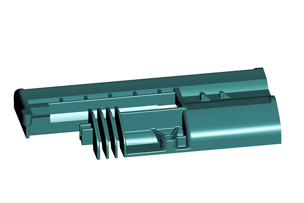
This part was made from PPSU plastic resin
There are thousands of thermoforming resins, and each has unique chemical and mechanical properties. In this study, one of the parts was made with 30% glass-filled PEEK. PEEK is a high-temperature engineering plastic used in automotive, aerospace and medical applications. The addition of glass fibers makes it even stronger and more durable. When using PEEK, it’s important to know that you must use the correct mold tool steel.
We used S136 stainless steel for the tool. Why? There are several important advantages to this metal. For one, stainless steel is the most resistant to the corrosive chemical affects of the resin. It resists the abrasion of the glass fiber, and takes a high polish for an excellent surface quality finish. And most importantly it works well for large production runs at higher temperatures such as PEEK requires.
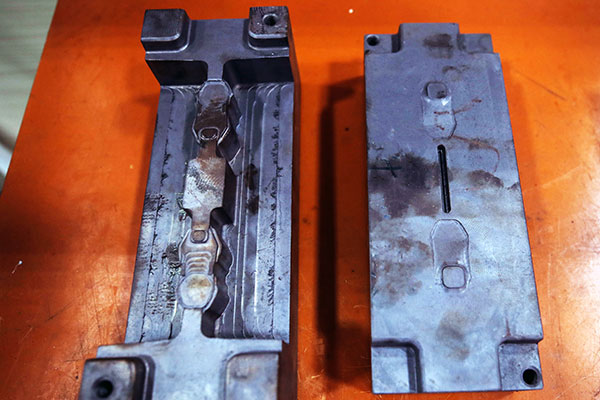
These inserts were rough milled before heat treatment and polishing
Because PEEK needs to be injected at high temperatures and pressures, the tool steel must be heat-treated for extra strength and thermal stability. So this heat treatment process was done after CNC machining, but before final polishing.
Notice that we only machined a partial mold tool insert. The insert, once prepared, was then placed inside of a larger modular die, and that die put into the machine. This helps to reduce the total tooling costs.
Heated mold inserts made from S136 stainless steel
The mold also uses a hot runner system. PEEK resin needs to be injected at 190 deg. C, but the plastic injection molding machine can only attain about 170 deg. Therefore it was necessary to use an electrical heating system. This also regulates temperature more effectively for outstanding results.
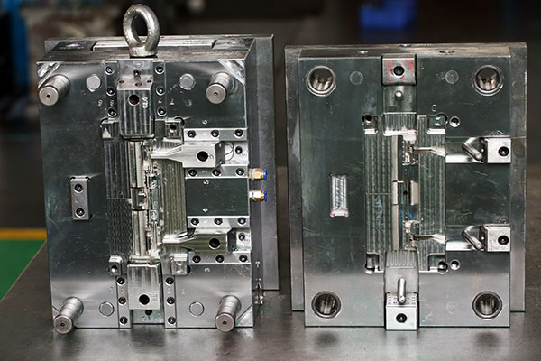
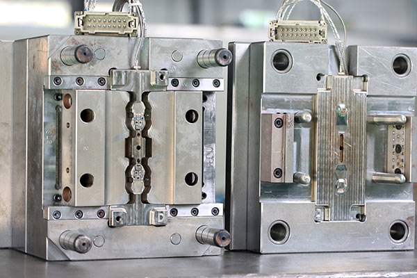
PPSU molds made from S136 stainless
The other plastic resin is PPSU, which does not require such high temperatures. The customer chose to use S136 again because this is a full production tool for high volumes.
Every resin has a unique shrink rate and shrink percentage, and this determines how strongly it grips the walls of the tool after molding. This tendency to stick inside the mold must be counteracted by a sound strategy for draft angles.
Use the resin manufacturer’s product specification sheet to help you calculate minimum draft angles. Note that these may also be modified based on the design feature.
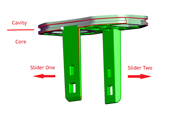
Moving the parting line also required a larger draft angle
If there is a lot of draft at the parting line this could cause mold flash. Therefore we moved the parting line to be on the core side of the mold, so that potential flash would not affect the cosmetic face of the part.
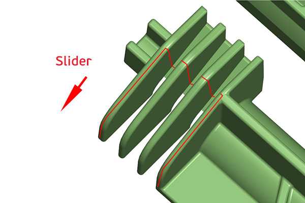
Thin but deep ribs require careful attention to draft angles
Draft can be more challenging to plan for on smaller areas of detail, especially if the features are not in the line of draw of the mold. In this example, a slider will be used to make these fins, and the slider must also have a draft angle so that it doesn’t bind up the part or even break it off after molding.
Managing wall thickness is important for controlling stress marks. But there is also a minimum wall thickness to consider.
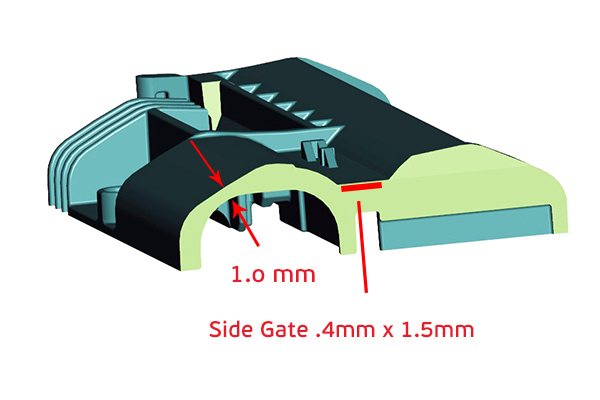
There is high injection pressure near the gate
In this area, the original design called for a wall thickness of only .6mm. In practical terms this can create at least three problems.
Firstly, it takes a lot of injection pressure to fill this narrow area. That much pressure creates internal stress that can damage the part or cause the plastic resin to degrade.
Secondly, this pressure is exerted right at the split line, increasing the likelihood of flash. That flash will take extra time and effort to remove and will leave a corresponding mark on the finished piece.
Thirdly, this stress also adversely affects the mold tool, significantly degrading potential tool life. This can be an expensive problem and needs to be avoided. Therefore our advice was to increase wall thickness to at least 1mm. This reduced the stress in this area to a much more manageable degree.
A good strategy for ejection should be part of the design process from the beginning, not an afterthought.
There are a couple of sound reasons for this, especially on thin parts. Thin part edges offer areas too small to push against for a standard pin. In some cases, stripper plates must be made instead. Stripper plates work against larger surface areas but they’re also more time-consuming and expensive to make on the mold tool.
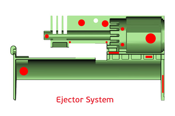
Some part geometries are challenging to balance
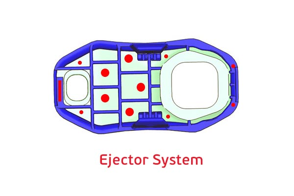
Symmetrical parts are easier to balance
Also, the application of ejection force needs to be balanced out over the surface area of the part, taking into account different wall thicknesses and mass. If these forces are uneven then the part can warp or even break.
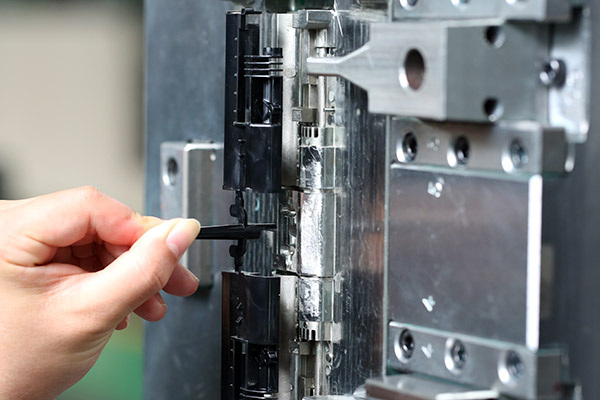
PPSU part being ejected
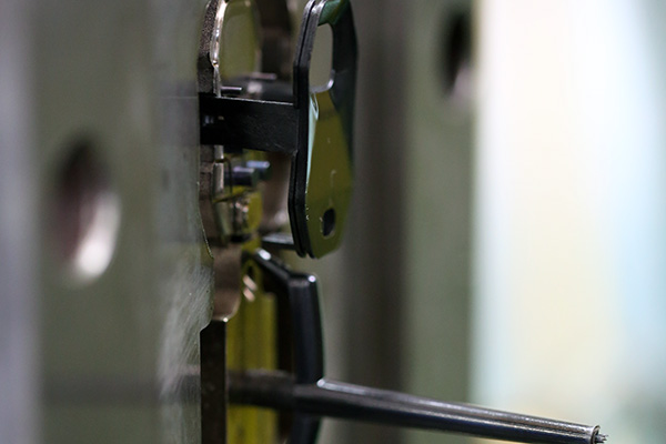
The ejector pins are clearly visible in the tool
Ejector pins are especially important in the area surrounding the gate. These pins are helpful if there is a short-shot in the cavity, resulting in a gate that’s blocked by plastic and needs to be cleared.
The designer therefore can consider a couple of potential solutions. One is to make walls thicker, though of course always keeping them balanced. Another is to create pads or other flat areas that are designed specifically to offer a push area for the force of the pin to act against.