中文
ENGLISH
中文
ENGLISH
Designing plastic parts is a complex task involving many factors that address a list of requirements of the application. "How is the part to be used?" "How does it fit to other parts in the assembly?" "What loads will it experience in use?" In addition to functional and structural issues, processing issues play a large role in the design of an vowin.cn/' target='_blank'>injection vowin.cn/' target='_blank'>molded plastic part. How the molten plastic enters, fills, and cools within the cavity to form the part largely drives what form the features in that part must take. Adhering to some basic rules of injection molded part design will result in a part that, in addition to being easier to manufacture and assemble, will typically be much stronger in service. Dividing a part into basic groups will help you to build your part in a logical manner while minimizing molding problems. As a part is developed, always keep in mind how the part is molded and what you can do to minimize stress.
目录
(a) Applications
(b) Polymers Best Suited for Injection Molding
(c) Injection Molding Equipment
(d) Injection Molding Process
(e) Injection Molding Cycle
(f) Different Types of Injection Molding Processes
(g) Stress
(h) Gates
(i) Common Gates
(j) Gate Location
(k) Wall Thickness
(l) Draft
(m) Sink Marks
(n) Textures
(o) Parting Lines
(p) Common Molding Defects
Applications (^ Back to Top)
Plastic injection molding is the preferred process for manufacturing plastic parts. Injection molding is used to create many things such as electronic housings, containers, bottle caps, automotive interiors, combs, and most other plastic products available today. It is ideal for producing high volumes of plastic parts due to the fact that several parts can be produced in each cycle by using multi-cavity injection molds. Some advantages of injection molding are high tolerance precision, repeatability, large material selection, low labor cost, minimal scrap losses, and little need to finish parts after molding. Some disadvantages of this process are expensive upfront tooling investment and process limitations.
Polymers Best Suited for Injection Molding (^ Back to Top)
Most polymers may be used, including all thermoplastics and some elastomers. There are tens of thousands of different materials available for injection molding. The available materials mixed with alloys or blends of previously developed materials means that product designers can choose from a vast selection of materials to find the one that has exactly the right properties. Materials are chosen based on the strength and function required for the final part; but also each material has different parameters for molding that must be considered. Common polymers like nylon, polyethylene, and polystyrene are thermoplastic.
Injection Molding Equipment (^ Back to Top)
Injection Molding Machine:
Injection molding machines, also known as presses, consist of a material hopper, an injection ram or screw-type plunger, and a heating unit. Molds are clamped to the platen of the molding machine, where plastic is injected into the mold through the sprue orifice. Presses are rated by tonnage, which is the calculation of the amount of clamping force that the machine can exert. This force keeps the mold closed during the injection molding process. Tonnage can vary from less than 5 tons to 6,000 tons, although the higher tonnage presses are rarely used. The total clamp force needed is determined by the projected area of the custom part being molded. This projected area is multiplied by a clamp force of from 2 to 8 tons for each square inch of the projected areas. As a rule of thumb, 4 or 5 tons/in can be used for most products. If the plastic material is very stiff, it will require more injection pressure to fill the mold, thus more clamp tonnage is needed to hold the mold closed. The required force can also be determined by the material used and the size of the part with larger plastic parts requiring higher clamping force.
Mold:
The mold or die refers to the tooling used to produce plastic parts in molding. Traditionally injection molds have been expensive to manufacture and were only used in high-volume production applications where thousands of parts were produced. Molds are typically constructed from hardened steel, pre-hardened steel, aluminum, and/or beryllium-copper alloy. The choice of material to build a mold from is primarily one of economics. Steel molds generally cost more to construct but offer a longer lifespan that will offset the higher initial cost over a higher number of parts made before wearing out. Pre-hardened steel molds are less wear resistant and are primarilly used for lower volume requirements or larger components. The hardness of the pre-hardened steel measures typically 38-45 on the Rockwell-C scale. Hardened steel molds are heat treated after machining, making them superior in terms of wear resistance and lifespan. Typical hardness ranges between 50 and 60 Rockwell-C (HRC).
Aluminum molds cost substantially less than steel molds, and when higher grade aluminum such as QC-7 and QC-10 aircraft aluminum is used and machined with modern computerized equipment, they can be economical for molding hundreds of thousands of parts. Aluminum molds also offer quick turnaround and faster cycles because of better heat dissipation. They can also be coated for wear resistance to fiberglass reinforced materials. Beryllium copper is used in areas of the mold which require fast heat removal or areas that see the most shear heat generated.
Injection Molding Process (^ Back to Top)
With injection molding, granular plastic is fed by gravity from a hopper into a heated barrel. As the granules are slowly pushed forward by a screw-type plunger, the plastic is forced into a heated chamber called the barrel where it is melted. As the plunger advances, the melted plastic is forced through a nozzle that seats against the mold sprue bushing, allowing it to enter the mold cavity through a gate and runner system. The mold remains at a set temperature so the plastic can solidify almost as soon as the mold is filled.
Injection Molding Cycle (^ Back to Top)
The sequence of events during the injection molding of a plastic part is called the injection molding cycle. The cycle begins when the mold closes, followed by the injection of the polymer into the mold cavity. Once the cavity is filled, a holding pressure is maintained to compensate for material shrinkage. In the next step, the screw turns, feeding the next shot to the front screw. This causes the screw to retract as the next shot is prepared. Once the part is sufficiently cool, the mold opens and the part is ejected.
Different Types of Injection Molding Processes (^ Back to Top)
Although most injection molding processes are covered by the conventional process description above, there are several important molding variations including:
Stress (^ Back to Top)
The main enemy of any injection molded plastic part is stress. When a plastic resin (which contains long strains of molecules) is melted in preparation for molding, the molecular bonds are temporarily broken due to the heat and shear force of the extruder, allowing the molecules to flow into the mold. Using pressure, the resin is forced into the mold filling in every feature, crack and crevice of the mold. As the molecules are pushed through each feature, they are forced to bend, turn and distort to form the shape of the part. Turning hard or sharp corners exerts more stress on the molecule than taking gentle turns with generous radii. Abrupt transitions from one feature to another are also difficult for the molecules to fill and form to.
As the material cools and the molecular bonds re-link the resin into its rigid form, these stresses are in effect locked into the part. Part stresses can cause warpage, sink marks, cracking, premature failure and other problems.
While some stresses in an injection molded part are to be expected, you should design your parts with as much consideration for stress reduction as possible. Some ways to do this are by adding smooth transitions between features and using rounds and fillets in possible high stress areas.
Gates (^ Back to Top)
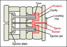 Each injection mold design must have a gate, or an opening that allows the molten plastic to be injected into the cavity of the mold. Gate type, design and location can have effects on the part such as part packing, gate removal or vestige, cosmetic appearance of the part, and part dimensions & warping.
Gate Types
There are two types of gates available for injection molding; manually trimmed and automatically trimmed gates.
Manually Trimmed Gates:
These type of gates require an operator to separate the aprts from the runners manually after each cycle. Manually trimmed gates are chosen for several reasons:
Automatically Trimmed Gates
These type of gates incorporate features in the tool to break or shear the gates when the tool opens to eject the part. Automatically trimmed gates are used for several reasons:
Common Gate Designs (^ Back to Top)
The largest factor to consider when choosing the proper gate type for your application is the gate design. There are many different gate designs available based on the size and shape of your part. Below are four of the most popular gate designs used by Quickparts customers:
The Edge Gate is the most common gate design. As the name indicates, this gate is located on the edge of the part and is best suited for flat parts. Edge gates are ideal for medium and thick sections and can be used on multicavity two plate tools. This gate will leave a scar at the parting line.
The Sub Gate is the only automatically trimmed gate on the list. Ejector pins will be necessary for automatic trimming of this gate. Sub gates are quite common and have several variations such as banana gate, tunnel gate and smiley gate to name a few. The sub gate allows you to gate away from the parting line, giving more flexibility to place the gate at an optimum location on the part. This gate leaves a pin sized scar on the part.
The Hot Tip Gate is the most common of all hot runner gates. Hot tip gates are typically located at the top of the part rather than on the parting line and are ideal for round or conical shapes where uniform flow is necessary. This gate leaves a small raised nub on the surface of the part. Hot tip gates are only used with hot runner molding systems. This means that, unlike cold runner systems, the plastic is ejected into the mold through a heated nozzle and then cooled to the proper thickness and shape in the mold.
The Direct or Sprue Gate is a manually trimmed gate that is used for single cavity molds of large cylindrical parts that require symmetrical filling. Direct gates are the easiest to design and have low cost and maintenance requirements. Direct gated parts are typically lower stressed and provide high strength. This gate leaves a large scar on the part at the point of contact.
Gate Location (^ Back to Top)
To avoid problems from your gate location, below are some guidelines for choosing the proper gate location(s):
Gates vary in size and shape depending upon the type of plastic being molded and the size of the part. Large parts will require larger gates to provide a bigger flow of resin to shorten the mold time. Small gates have a better appearance but take longer time to mold or may need to have higher pressure to fill correctly.
Wall Thickness (^ Back to Top)
Prior to ejection from the mold, injection molded parts are cooled down from manufacturing temperatures so that they hold their shape when ejected. During the part cooling step of the molding process, changes in pressure, velocity and plastic viscosity should be minimized to avoid defects. Few aspects are more crucial during this period than wall thickness. This feature can have major effects on the cost, production speed and quality of the final parts.
Proper Wall Thickness:
Choosing the proper wall thickness for your part can have drastic effects on the cost and production speed of manufacturing. While there are no wall thickness restrictions, the goal is usually to choose the thinnest wall possible. Thinner walls use less material which reduces cost and take less time to cool, reducing cycle time.
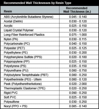
The minimum wall thickness that can be used depends on the size and geometry of the part, structural requirements, and flow behavior of the resin. The wall thicknesses of an injection molded part generally range from 2mm – 4mm (0.080" – 0.160"). Thin wall injection molding can produce walls as thin as 0.5mm (0.020"). The chart below shows recommended wall thicknesses for common injection molding resins.
Uniform Wall Thickness:
Thick sections take longer to cool than thin ones. During the cooling process, if walls are an inconsistent thickness, the thinner walls will cool first while the thick walls are still solidifying. As the thick section cools, it shrinks around the already solid thinner section. This causes warping, twisting or cracking to occur where the two sections meet. To avoid this problem, try to design with completely uniform walls throughout the part. When uniform walls are not possible, then the change in thickness should be as gradual as possible. Wall thickness variations should not exceed 10% in high mold shrinkage plastics. Thickness transitions should be made gradually, on the order of 3 to 1. This gradual transition avoids stress concentrations and abrupt cooling differences.
Alternatives:
If your part is so complex that you need variations on your wall thickness, look for an alternative. You may want to use design features such as coring or using ribs. At the very least, try not to make the transitions between thicker and thinner sections too abrupt. Try using a gradual transition or chamfered corners to minimize the dramatic change in pressures inside the mold.
Draft (^ Back to Top)
Most injection molded plastic parts include features such as outside walls and internal ribs that are formed by opposing surfaces of tool metal inside a closed mold. To properly release the part when the mold opens, the side walls of the mold are tapered in the direction that the mold opens. This tapering is referred to as "draft in the line of draw". This draft allows the part to break free of the mold as soon as the mold opens. The amount of draft required can depend on the surface finish of the mold. A smooth, polished tool surface will allow the part to eject with less draft than a standard tool surface.
Consider the fabrication of the hollow plastic box seen to the right. Once the plastic has hardened around the mold, the mold must be removed. As the plastic hardens, it will contract slightly. By tapering the sides of the mold by an appropriate "draft angle", the mold will be easier to remove.
The amount of draft required (in degrees) will vary with geometry and surface texture requirements of the part. Below are several rules for using draft properly:
 Be sure to add draft to your 3D CAD model before creating radii
Sink Marks (^ Back to Top)
When the hot melt flows into the injection mold, the thick sections don’t cool as fast as the rest of the part because the thicker material becomes insulated by the outside surface of faster cooling plastic. As the inner core cools, it shrinks at a different rate than the already cooled outer skin. This difference on cooling rates causes the thick section to draw inward and create a sink mark on the outside surface of the part, or worse, completely warp the part. In addition to being unattractive, the mark also represents added stress that is built into the part. Other less conspicuous areas where sink occurs include ribs, bosses and corners. These are often overlooked because neither the feature nor the part itself is too thick; however, the intersection of the two can be a problem.
One way to avoid sink marks is to core out the solid sections of the part to reduce thick areas. If the strength of a solid part is required, try using cross hatched rib patterns inside the cored out area to increase strength and avoid sink. As a rule-of-thumb, make sure that all bosses and locating/support ribs are no more than 60% of the thickness of the nominal wall. Also, textures can be used to hide minor sink marks.
Textures (^ Back to Top)
Texturing is a process used to apply patterns to a mold surface. This process allows flexibility in creating the final appearance of your parts. Texturing is an integral piece in overall product development and should be considered during the design process to achieve the desired results. Texture can be a functional component of design as well. Imperfect parts can be camouflaged by the right texture. Is the part designed for frequent handling? Texture can be used to hide finger prints and improve the grip for the end user. Texture can also be used to reduce part wear from friction.
A wide variety of textures are available for injection molded parts such as:

When applying a texture to a part, the CAD drawing must be adjusted to accommodate for this surface variance. If the texture is on a surface that is perpendicular or angled away from the mold opening then no draft changes are necessary. If the texture is on a parallel surface with the mold opening, however, increased draft is necessary to prevent scraping and drag marks that could occur during part ejection. Different textures have different impacts on the molded part. The rule-of-thumb when designing for texture is to have 1.5 degrees of draft for each 0.001" of texture finish depth.
Parting Lines (^ Back to Top)
A "parting line" is the line of separation on the part where the two halves of the mold meet. The line actually indicates the parting "plane" that passes through the part. While on simple parts this plane can be a simple, flat surface, it is often a complex form that traces the perimeter of the part around the various features that make up the part’s outer "silhouette". Part lines can also occur where any two pieces of a mold meet. This can include side action pins, tool inserts and shutoffs. Parting lines cannot be avoided; every part has them. Keep in mind when designing your part, that the melt will always flow towards the parting line because it is the easiest place for the displaced air to escape or "vent".
Common Molding Defects (^ Back to Top)
Injection molding is a complex technology with possible production problems. They can either be caused by defects in the molds or more often by part processing (molding)
Molding DefectsAlternative NameDescriptionsCauses
BlisterBlisteringRaised or layered zone on surface of the Plastic partTool or material is too hot, often caused by a lack of cooling around the tool or a faulty heater
Burn marksAir Burn/Gas BurnBlack or brown burnt areas on the plastic part located at furthest points from gateTool lacks venting, injection speed is too high
Color streaks (US) Localized change of colorPlastic material and colorant isn't mixing properly, or the material has run out and it's starting to come through as natural only
Delamination Thin mica like layers formed in part wallContamination of the material e.g. PP mixed with ABS, very dangerous if the part is being used for a safety critical application as the material has very little strength when delaminated as the materials cannot bond
FlashBurrsExcess material in thin layer exceeding normal part geometryTool damage, too much injection speed/material injected, clamping force too low. Can also be caused by dirt and contaminants around tooling surfaces.
Embedded contaminatesEmbedded particulatesForeign particle (burnt material or other) embedded in the partParticles on the tool surface, contaminated material or foreign debris in the barrel, or too much shear heat burning the material prior to injection
Flow marksFlow linesDirectionally "off tone" wavy lines or patternsInjection speeds too slow (the plastic has cooled down too much during injection, injection speeds must be set as fast as you can get away with at all times)
Jetting
Deformed part by turbulent flow of materialPoor tool design, gate position or runner. Injection speed set too high.
Polymer degradation polymer breakdown from oxidation, etc.Excess water in the granules, excessive temperatures in barrel
Sink marks Localized depression
(In thicker zones)Holding time/pressure too low, cooling time too short, with sprueless hot runners this can also be caused by the gate temperature being set too high
Short shotNon-Fill/Short MoldPartial partLack of material, injection speed or pressure too low
Splay marksSplash Mark/Silver StreaksCircular pattern around gate caused by hot gasMoisture in the material, usually when resins are dried improperly
StringinessStringingString like remain from previous shot transfer in new shotNozzle temperature too high. Gate hasn't frozen off
Voids Empty space within part
(Air pocket)Lack of holding pressure (holding pressure is used to pack out the part during the holding time). Also mold may be out of registration (when the two halves don't center properly and part walls are not the same thickness).
Weld line
Knit Line/Meld LineDiscolored line where two flow fronts meetMold/material temperatures set too low (the material is cold when they meet, so they don't bond)
WarpingTwisting PartDistorted partCooling is too short, material is too hot, lack of cooling around the tool, incorrect water temperatures (the parts bow inwards towards the hot side of the tool)
Keep these factors in mind when designing your injection molded part, and remember that it is easier to avoid problems in the beginning than change your design down the line.
| Molding Defects | Alternative Name | Descriptions | Causes |
|---|---|---|---|
| Blister | Blistering | Raised or layered zone on surface of the Plastic part | Tool or material is too hot, often caused by a lack of cooling around the tool or a faulty heater |
| Burn marks | Air Burn/Gas Burn | Black or brown burnt areas on the plastic part located at furthest points from gate | Tool lacks venting, injection speed is too high |
| Color streaks (US) | Localized change of color | Plastic material and colorant isn't mixing properly, or the material has run out and it's starting to come through as natural only | |
| Delamination | Thin mica like layers formed in part wall | Contamination of the material e.g. PP mixed with ABS, very dangerous if the part is being used for a safety critical application as the material has very little strength when delaminated as the materials cannot bond | |
| Flash | Burrs | Excess material in thin layer exceeding normal part geometry | Tool damage, too much injection speed/material injected, clamping force too low. Can also be caused by dirt and contaminants around tooling surfaces. |
| Embedded contaminates | Embedded particulates | Foreign particle (burnt material or other) embedded in the part | Particles on the tool surface, contaminated material or foreign debris in the barrel, or too much shear heat burning the material prior to injection |
| Flow marks | Flow lines | Directionally "off tone" wavy lines or patterns | Injection speeds too slow (the plastic has cooled down too much during injection, injection speeds must be set as fast as you can get away with at all times) |
|
Jetting |
Deformed part by turbulent flow of material | Poor tool design, gate position or runner. Injection speed set too high. | |
| Polymer degradation | polymer breakdown from oxidation, etc. | Excess water in the granules, excessive temperatures in barrel | |
| Sink marks |
Localized depression (In thicker zones) |
Holding time/pressure too low, cooling time too short, with sprueless hot runners this can also be caused by the gate temperature being set too high | |
| Short shot | Non-Fill/Short Mold | Partial part | Lack of material, injection speed or pressure too low |
| Splay marks | Splash Mark/Silver Streaks | Circular pattern around gate caused by hot gas | Moisture in the material, usually when resins are dried improperly |
| Stringiness | Stringing | String like remain from previous shot transfer in new shot | Nozzle temperature too high. Gate hasn't frozen off |
| Voids |
Empty space within part (Air pocket) |
Lack of holding pressure (holding pressure is used to pack out the part during the holding time). Also mold may be out of registration (when the two halves don't center properly and part walls are not the same thickness). | |
|
Weld line |
Knit Line/Meld Line | Discolored line where two flow fronts meet | Mold/material temperatures set too low (the material is cold when they meet, so they don't bond) |
| Warping | Twisting Part | Distorted part | Cooling is too short, material is too hot, lack of cooling around the tool, incorrect water temperatures (the parts bow inwards towards the hot side of the tool) |