prototype moldinjection moldingplastic mouldplastic injection mould

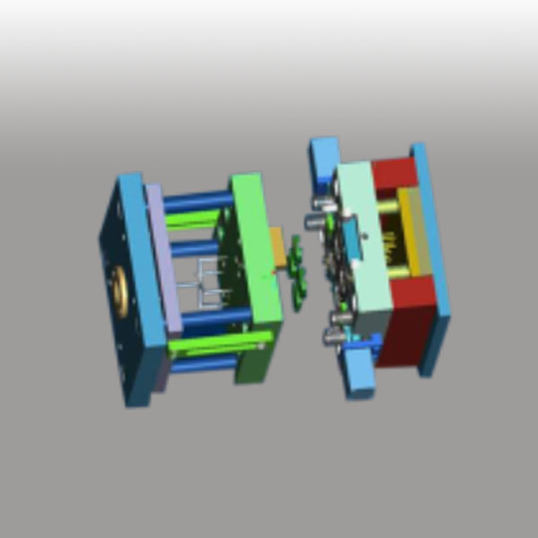
The mould consists of two primary components, the injection mould (A plate) and the ejector mould (B plate). These components are also referred to as moulder and mouldmaker.[12] Plastic resin enters the mould through a sprue or gate in the injection mould; the sprue bushing is to seal tightly against the nozzle of the injection barrel of the moulding machine and to allow molten plastic to flow from the barrel into the mould, also known as the cavity.[8]:141 The sprue bushing directs the molten plastic to the cavity images through channels that are machined into the faces of the A and B plates. These channels allow plastic to run along them, so they are referred to as runners.[8]:142 The molten plastic flows through the runner and enters one or more specialized gates and into the cavity[13]:15 geometry to form the desired part.

The amount of resin required to fill the sprue, runner and cavities of a mould comprises a "shot". Trapped air in the mould can escape through air vents that are ground into the parting line of the mould, or around ejector pins and slides that are slightly smaller than the holes retaining them. If the trapped air is not allowed to escape, it is compressed by the pressure of the incoming material and squeezed into the corners of the cavity, where it prevents filling and can also cause other defects. The air can even become so compressed that it ignites and burns the surrounding plastic material.[8]:147
To allow for removal of the moulded part from the mould, the mould features must not overhang one another in the direction that the mould opens, unless parts of the mould are designed to move from between such overhangs when the mould opens (using components called Lifters).
Sides of the part that appear parallel with the direction of draw (the axis of the cored position (hole) or insert is parallel to the up and down movement of the mould as it opens and closes)[13]:406 are typically angled slightly, called draft, to ease release of the part from the mould. Insufficient draft can cause deformation or damage. The draft required for mould release is primarily dependent on the depth of the cavity: the deeper the cavity, the more draft necessary. Shrinkage must also be taken into account when determining the draft required.[13]:332 If the skin is too thin, then the moulded part will tend to shrink onto the cores that form while cooling and cling to those cores, or the part may warp, twist, blister or crack when the cavity is pulled away.[8]:47
A mould is usually designed so that the moulded part reliably remains on the ejector (B) side of the mould when it opens, and draws the runner and the sprue out of the (A) side along with the parts. The part then falls freely when ejected from the (B) side. Tunnel gates, also known as submarine or mould gates, are located below the parting line or mould surface. An opening is machined into the surface of the mould on the parting line. The moulded part is cut (by the mould) from the runner system on ejection from the mould.[13]:288 Ejector pins, also known as knockout pins, are circular pins placed in either half of the mould (usually the ejector half), which push the finished moulded product, or runner system out of a mould.[8]:143The ejection of the article using pins, sleeves, strippers, etc. may cause undesirable impressions or distortion, so care must be taken when designing the mould.
The standard method of cooling is passing a coolant (usually water) through a series of holes drilled through the mould plates and connected by hoses to form a continuous pathway. The coolant absorbs heat from the mould (which has absorbed heat from the hot plastic) and keeps the mould at a proper temperature to solidify the plastic at the most efficient rate.[8]:86
To ease maintenance and venting, cavities and cores are divided into pieces, called inserts, and sub-assemblies, also called inserts, blocks, or chase blocks. By substituting interchangeable inserts, one mould may make several variations of the same part.
More complex parts are formed using more complex moulds. These may have sections called slides, that move into a cavity perpendicular to the draw direction, to form overhanging part features. When the mould is opened, the slides are pulled away from the plastic part by using stationary “angle pins” on the stationary mould half. These pins enter a slot in the slides and cause the slides to move backward when the moving half of the mould opens. The part is then ejected and the mould closes. The closing action of the mould causes the slides to move forward along the angle pins.[8]:268
Some moulds allow previously moulded parts to be reinserted to allow a new plastic layer to form around the first part. This is often referred to as overmoulding. This system can allow for production of one-piece tires and wheels.
Two-shot or multi-shot moulds are designed to "overmould" within a single moulding cycle and must be processed on specialized injection moulding machines with two or more injection units. This process is actually an injection moulding process performed twice and therefore has a much smaller margin of error. In the first step, the base color material is moulded into a basic shape, which contains spaces for the second shot. Then the second material, a different color, is injection-moulded into those spaces. Pushbuttons and keys, for instance, made by this process have markings that cannot wear off, and remain legible with heavy use.[8]:174
A mould can produce several copies of the same parts in a single "shot". The number of "impressions" in the mould of that part is often incorrectly referred to as cavitation. A tool with one impression will often be called a single impression (cavity) mould.[14]:398 A mould with 2 or more cavities of the same parts will likely be referred to as multiple impression (cavity) mould.[14]:262 Some extremely high production volume moulds (like those for bottle caps) can have over 128 cavities.
In some cases multiple cavity tooling will mould a series of different parts in the same tool. Some toolmakers call these moulds family moulds as all the parts are related. Examples include plastic model kits.[15]:114
Manufacturers go to great lengths to protect custom moulds due to their high average costs. The perfect temperature and humidity level is maintained to ensure the longest possible lifespan for each custom mould. Custom moulds, such as those used for rubber injection moulding, are stored in temperature and humidity controlled environments to prevent warping.[16]
Tool steel is often used. Mild steel, aluminum, nickel or epoxy are suitable only for prototype or very short production runs.[1] Modern hard aluminum (7075 and 2024 alloys) with proper mould design, can easily make moulds capable of 100,000 or more part life with proper mould maintenance.[17]

Moulds are built through two main methods: standard vowin.cn/en/News/news1251.html' target='_blank'>machining and EDM. Standard machining, in its conventional form, has historically been the method of building injection moulds. With technological development, CNC machining became the predominant means of making more complex moulds with more accurate mould details in less time than traditional methods.
The electrical discharge machining (EDM) or spark erosion process has become widely used in mould making. As well as allowing the formation of shapes that are difficult to machine, the process allows pre-hardened moulds to be shaped so that no heat treatment is required. Changes to a hardened mould by conventional drilling and milling normally require annealing to soften the mould, followed by heat treatment to harden it again. EDM is a simple process in which a shaped electrode, usually made of copper or graphite, is very slowly lowered onto the mould surface (over a period of many hours), which is immersed in paraffin oil (kerosene). A voltage applied between tool and mould causes spark erosion of the mould surface in the inverse shape of the electrode.[18]
The number of cavities incorporated into a mould will directly correlate in moulding costs. Fewer cavities require far less tooling work, so limiting the number of cavities in-turn will result in lower initial manufacturing costs to build an injection mould.
As the number of cavities play a vital role in moulding costs, so does the complexity of the part's design. Complexity can be incorporated into many factors such as surface finishing, tolerance requirements, internal or external threads, fine detailing or the number of undercuts that may be incorporated.[19]
Further details such as undercuts, or any feature causing additional tooling will increase the mould cost. Surface finish of the core and cavity of molds will further influence the cost.
Rubber injection moulding process produces a high yield of durable products, making it the most efficient and cost-effective method of moulding. Consistent vulcanization processes involving precise temperature control significantly reduces all waste material.[20]

With injection moulding, granular plastic is fed by a forced ram from a hopper into a heated barrel. As the granules are slowly moved forward by a screw-type plunger, the plastic is forced into a heated chamber, where it is melted. As the plunger advances, the melted plastic is forced through a nozzle that rests against the mould, allowing it to enter the mould cavity through a gate and runner system. The mould remains cold so the plastic solidifies almost as soon as the mould is filled.[1]
The sequence of events during the injection mould of a plastic part is called the injection moulding cycle. The cycle begins when the mould closes, followed by the injection of the polymer into the mould cavity. Once the cavity is filled, a holding pressure is maintained to compensate for material shrinkage. In the next step, the screw turns, feeding the next shot to the front screw. This causes the screw to retract as the next shot is prepared. Once the part is sufficiently cool, the mould opens and the part is ejected.[21]:13
Traditionally, the injection portion of the molding process was done at one constant pressure to fill and pack the cavity. This method, however, allowed for a large variation in dimensions from cycle-to-cycle. More commonly used now is scientific or decoupled moulding, a method pioneered by RJG Inc.[22][23][24] In this the injection of the plastic is "decoupled" into stages to allow better control of part dimensions and more cycle-to-cycle (commonly called shot-to-shot in the industry) consistency. First the cavity is filled to approximately 98% full using velocity (speed) control. Although the pressure should be sufficient to allow for the desired speed, pressure limitations during this stage are undesirable. Once the cavity is 98% full, the machine switches from velocity control to pressure control, where the cavity is "packed out" at a constant pressure, where sufficient velocity to reach desired pressures is required. This allows part dimensions to be controlled to within thousandths of an inch or better.[25]


Although most injection moulding processes are covered by the conventional process description above, there are several important moulding variations including, but not limited to:
A more comprehensive list of injection moulding processes may be found here: [1]
Like all industrial processes, injection moulding can produce flawed parts. In the field of injection moulding, troubleshooting is often performed by examining defective parts for specific defects and addressing these defects with the design of the mould or the characteristics of the process itself. Trials are often performed before full production runs in an effort to predict defects and determine the appropriate specifications to use in the injection process.[3]:180
When filling a new or unfamiliar mould for the first time, where shot size for that mould is unknown, a technician/tool setter may perform a trial run before a full production run. He starts with a small shot weight and fills gradually until the mould is 95 to 99% full. Once this is achieved, a small amount of holding pressure will be applied and holding time increased until gate freeze off (solidification time) has occurred. Gate freeze off time can be determined by increasing the hold time, and then weighing the part. When the weight of the part does not change, it is then known that the gate has frozen and no more material is injected into the part. Gate solidification time is important, as it determines cycle time and the quality and consistency of the product, which itself is an important issue in the economics of the production process.[26] Holding pressure is increased until the parts are free of sinks and part weight has been achieved.
Injection moulding is a complex technology with possible production problems. They can be caused either by defects in the moulds, or more often by the moulding process itself.[3]:47–85
| Moulding defects | Alternative name | Descriptions | Causes |
|---|---|---|---|
| Blister | Blistering | Raised or layered zone on surface of the part | Tool or material is too hot, often caused by a lack of cooling around the tool or a faulty heater |
| Burn marks | Air burn/gas burn/dieseling | Black or brown burnt areas on the part located at furthest points from gate or where air is trapped | Tool lacks venting, injection speed is too high |
| Color streaks (US) | Colour streaks (UK) | Localized change of color/colour | Masterbatch isn't mixing properly, or the material has run out and it's starting to come through as natural only. Previous colored material "dragging" in nozzle or check valve. |
| Delamination | Thin mica like layers formed in part wall | Contamination of the material e.g. PP mixed with ABS, very dangerous if the part is being used for a safety critical application as the material has very little strength when delaminated as the materials cannot bond | |
| Flash | Burrs | Excess material in thin layer exceeding normal part geometry | Mould is over packed or parting line on the tool is damaged, too much injection speed/material injected, clamping force too low. Can also be caused by dirt and contaminants around tooling surfaces. |
| Embedded contaminates | Embedded particulates | Foreign particle (burnt material or other) embedded in the part | Particles on the tool surface, contaminated material or foreign debris in the barrel, or too much shear heat burning the material prior to injection |
| Flow marks | Flow lines | Directionally "off tone" wavy lines or patterns | Injection speeds too slow (the plastic has cooled down too much during injection, injection speeds should be set as fast as is appropriate for the process and material used) |
| Gate Blush | Halo or Blush Marks | Circular pattern around gate, normally only an issue on hot runner molds | Injection speed is too fast, gate/sprue/runner size is too small, or the melt/mold temp is too low. |
| Jetting | Part deformed by turbulent flow of material. | Poor tool design, gate position or runner. Injection speed set too high. Poor design of gates which cause too little die swell and result jetting. | |
| Knit lines | Weld lines | Small lines on the backside of core pins or windows in parts that look like just lines. | Caused by the melt-front flowing around an object standing proud in a plastic part as well as at the end of fill where the melt-front comes together again. Can be minimized or eliminated with a mould-flow study when the mould is in design phase. Once the mould is made and the gate is placed, one can minimize this flaw only by changing the melt and the mould temperature. |
| Polymer degradation | Polymer breakdown from hydrolysis, oxidation etc. | Excess water in the granules, excessive temperatures in barrel, excessive screw speeds causing high shear heat, material being allowed to sit in the barrel for too long, too much regrind being used. | |
| Sink marks | [sinks] | Localized depression (In thicker zones) | Holding time/pressure too low, cooling time too short, with sprueless hot runners this can also be caused by the gate temperature being set too high. Excessive material or walls too thick. |
| Short shot | Non-fill or short mould | Partial part | Lack of material, injection speed or pressure too low, mould too cold, lack of gas vents |
| Splay marks | Splash mark or silver streaks | Usually appears as silver streaks along the flow pattern, however depending on the type and color of material it may represent as small bubbles caused by trapped moisture. | Moisture in the material, usually when hygroscopic resins are dried improperly. Trapping of gas in "rib" areas due to excessive injection velocity in these areas. Material too hot, or is being sheared too much. |
| Stringiness | Stringing or long-gate | String like remnant from previous shot transfer in new shot | Nozzle temperature too high. Gate hasn't frozen off, no decompression of the screw, no sprue break, poor placement of the heater bands inside the tool. |
| Voids | Empty space within part (air pocket is commonly used) | Lack of holding pressure (holding pressure is used to pack out the part during the holding time). Filling too fast, not allowing the edges of the part to set up. Also mould may be out of registration (when the two halves don't center properly and part walls are not the same thickness). The provided information is the common understanding, Correction: The Lack of pack (not holding) pressure (pack pressure is used to pack out even though is the part during the holding time). Filling too fast does not cause this condition, as a void is a sink that did not have a place to happen. In other words, as the part shrinks the resin separated from itself as there was not sufficient resin in the cavity. The void could happen at any area or the part is not limited by the thickness but by the resin flow and thermal conductivity, but it is more likely to happen at thicker areas like ribs or bosses. Additional root causes for voids are un-melt on the melt pool. | |
| Weld line | Knit line / Meld line / Transfer line | Discolored line where two flow fronts meet | Mould or material temperatures set too low (the material is cold when they meet, so they don't bond). Time for transition between injection and transfer (to packing and holding) is too early. |
| Warping | Twisting | Distorted part | Cooling is too short, material is too hot, lack of cooling around the tool, incorrect water temperatures (the parts bow inwards towards the hot side of the tool) Uneven shrinking between areas of the part |
Methods such as industrial CT scanning can help with finding these defects externally as well as internally.
Moulding tolerance is a specified allowance on the deviation in parameters such as dimensions, weights, shapes, or angles, etc. To maximize control in setting tolerances there is usually a minimum and maximum limit on thickness, based on the process used.[13]:439 Injection moulding typically is capable of tolerances equivalent to an IT Grade of about 9–14. The possible tolerance of a thermoplastic or a thermoset is ±0.200 to ±0.500 millimeters[citation needed]. In specialised applications tolerances as low as ±5 µm on both diameters and linear features are achieved in mass production. Surface finishes of 0.0500 to 0.1000 µm or better can be obtained. Rough or pebbled surfaces are also possible.
| Moulding Type | Typical [mm] | Possible [mm] |
|---|---|---|
| Thermoplastic | ±0.500 | ±0.200 |
| Thermoset | ±0.500 | ±0.200 |
The power required for this process of injection moulding depends on many things and varies between materials used. Manufacturing Processes Reference Guide states that the power requirements depend on "a material's specific gravity, melting point, thermal conductivity, part size, and molding rate." Below is a table from page 243 of the same reference as previously mentioned that best illustrates the characteristics relevant to the power required for the most commonly used materials.
| Material | Specific gravity | Melting point (°F) | Melting point (°C) |
|---|---|---|---|
| Epoxy | 1.12 to 1.24 | 248 | 120 |
| Phenolic | 1.34 to 1.95 | 248 | 120 |
| Nylon | 1.01 to 1.15 | 381 to 509 | 194 to 265 |
| Polyethylene | 0.91 to 0.965 | 230 to 243 | 110 to 117 |
| Polystyrene | 1.04 to 1.07 | 338 | 170 |
Automation means that the smaller size of parts permits a mobile inspection system to examine multiple parts more quickly. In addition to mounting inspection systems on automatic devices, multiple-axis robots can remove parts from the mould and position them for further processes.[27]
Specific instances include removing of parts from the mould immediately after the parts are created, as well as applying machine vision systems. A robot grips the part after the ejector pins have been extended to free the part from the mould. It then moves them into either a holding location or directly onto an inspection system. The choice depends upon the type of product, as well as the general layout of the manufacturing equipment. Vision systems mounted on robots have greatly enhanced quality control for insert moulded parts. A mobile robot can more precisely determine the placement accuracy of the metal component, and inspect faster than a human can.[27]

Lego injection mould, lower side

Lego injection mould, detail of lower side

Lego injection mould, upper side

Lego injection mould, detail of upper side